
On Camera
Published:
Have you ever wondered how cameras project an object in 3D space into a 2D image? This post covers the overarching process and dives deep into the first half of it. I am writing this post because, despite being a fundamental concept, there are surprisingly few guides that explain it clearly—mostly due to an overload of redundant terminology with identical meanings, and because most tutorials jump straight into equations without establishing basic intuition. I personally struggled with this during my own research, so I hope this post helps anyone tackling the subject in the future.
Space
Before diving into cameras, we first need to understand coordinate space. Space is perhaps the most fundamental concept here, yet as far as I know, camera tutorials rarely cover it explicitly. While I won’t give a formal mathematical definition, you can intuitively think of space like this: In object X’s space, X itself sits at (0, 0, 0). Regardless of X’s rotation, the lines crossing X’s centroid orthogonally along “left-right”, “up-down”, and “forward-backward” define its x-axis, y-axis, and z-axis, respectively. This means that coordinate axes in different objects’ spaces can differ. The true essence of an object’s space is that it captures the relative transformations of other objects. To illustrate this, consider the following example:
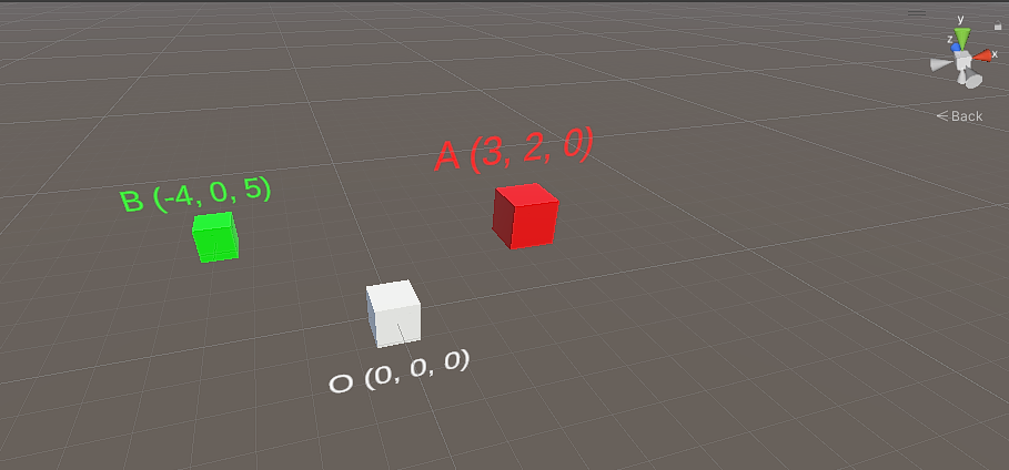
In this image, the coordinates of Cube O, Cube A, and Cube B are (0, 0, 0), (3, 2, 0), and (-4, 0, 5) in world space (or Cube O’s space, since it sits at the origin). This means that starting from the origin (Cube O), we must move +3 units along the x-axis and +2 units along the y-axis to reach Cube A, or -4 units along the x-axis and +5 units along the z-axis to reach Cube B.
Now, if we re-evaluate everything from Cube A’s space, Cube A itself is at (0, 0, 0). Cube O is located at (-3, -2, 0) because we must travel -3 units along the x-axis and -2 units along the y-axis to reach Cube O from Cube A. Similarly, the coordinate of Cube B in Cube A’s space is (-7, -2, 5).
“Space Transformation Matrix”
So far, we have discussed what a space is and walked through converting coordinates between spaces manually. However, we could easily derive these transformations because none of the cubes were rotated. Once we account for rotation and scaling, we need a more systematic tool: a “space transformation matrix” (quoted because I coined this term for clarity).
Let’s call this matrix M. M takes a coordinate from one object’s space as input and outputs the corresponding position in another object’s space:
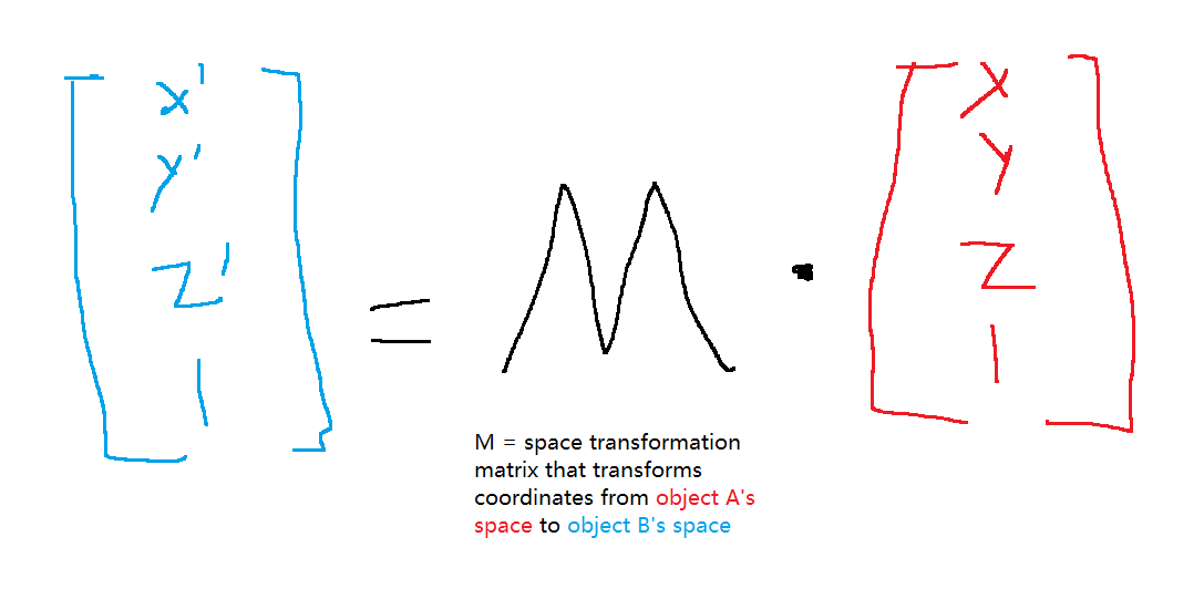
Specifically, the upper-left 3x3 submatrix applies scaling and rotation, while the final column applies translation (the technical term for positional shift). For a more detailed breakdown on extracting individual scale, rotation, and translation matrices, check out this well-written guide.
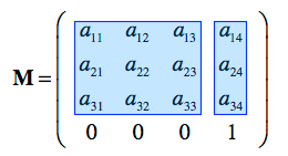
How do we calculate M? It depends on the source and target spaces. We simply define the necessary scale (S), rotation (R), and translation (T) matrices to transform from the source space to the target space, yielding M = S * R * T (or T * R * S, depending on convention).
Here is a fundamental M worth knowing, which I’ll use to demonstrate the magic of transformation matrices: the matrix that transforms coordinates from an arbitrary object’s space into world space. Given an object’s scale s, rotation r (a quaternion—if you’re unfamiliar with quaternions, just think of them as a 1x4 vector), and translation t in world space, M is:

This formula may look intimidating, but in our cube example, because the objects are neither rotated nor scaled, the upper-left 3x3 submatrix simplifies to an identity matrix.
For instance, suppose we want to calculate Cube B’s coordinate in world space. Given Cube B’s coordinate in Cube A’s space and the transformation matrix M from Cube A’s space to world space (substituting Cube A’s scale <1, 1, 1>, rotation <0, 0, 0, 0>, and translation <3, 2, 0> in world space into the matrix formula above), the calculation yields:
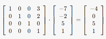
Where (-4, 0, 5) matches Cube B’s true coordinate in world space!
This demonstrates how a space transformation matrix enables us to convert coordinates from one space to another. The exact same principle applies when rotation and scaling are present; I omitted rotation earlier simply to keep the numbers as integers, making the initial diagrams easier to sketch.
Finally, Back to Cameras…
Thank you for bearing with the long preamble! With these concepts under our belt, we are finally ready to understand cameras. (And you might now realize how unnecessary it is to be intimidated by terms like view matrix, camera extrinsics, or camera intrinsics—they are simply space transformation matrices between different coordinate spaces.)
At its core, a camera transforms 3D objects into a 2D image—mapping 3D coordinates to 2D coordinates. It starts with an object’s coordinates in world space and transforms them in two phases:
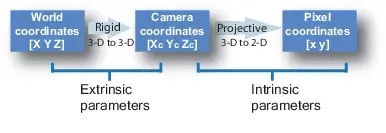
- Phase 1: Transform coordinates from world space into camera space. Like any coordinate transformation, this is performed by a space transformation matrix M, commonly referred to as the view matrix or camera extrinsics (or simply the matrix transforming world space to camera space). Based on what we covered earlier, you already know how to calculate M:
- A camera is no different from a cube or any other 3D object. Given its scale, rotation, and translation in world space, you can construct the matrix M’ that transforms coordinates from camera space to world space using the formula above.
- While M’ transforms camera space into world space, M transforms world space into camera space. For any vector X in camera space, applying both transformations sequentially must return the original point: M * M’ * X = X. This implies M * M’ = I, meaning M and M’ are matrix inverses of each other (M = inv(M’)).
- Phase 2: Transform coordinates from camera space into pixel space (dimensionality reduction). This matrix is called the camera intrinsics. It incorporates parameters like focal length and operates similarly to the pinhole camera model taught in introductory physics. For a deeper dive, this tutorial provides an excellent explanation!
And that is it! That is fundamentally how a camera operates. I hope this explanation demystifies the topic. (Note that non-pinhole cameras exist as well, which may use a different Phase 2 formulation or, rarely, a modified Phase 1.)
Novel View Synthesis in Unity: Lessons Learned
(Note: This section is less educational and more of a practical log explaining why I needed to dig into camera math. It serves as a note for my research lab members, though feel free to read along!)
I have been researching volumetric video and novel view synthesis for some time. Recently, I attempted to reproduce InstantAvatar’s novel view rendering by orbiting the camera around the avatar, whereas InstantAvatar’s original codebase keeps the camera stationary and rotates the SMPL body model instead.
To achieve this, I simulated a circular camera trajectory in Unity (orbiting around the y-axis) and recorded the resulting trace of Unity’s cameraToWorldMatrix (InstantAvatar takes a c2w matrix parameter, which defaults to np.eye() in the original repository). My goal was to synthesize views from arbitrary angles, but initial runs produced completely blank outputs.
After extensive troubleshooting, I identified one definite issue and hypothesized another—both of which required a firm grasp of camera transformation matrices:
- Issue 1: The SMPL model in InstantAvatar is not positioned at the origin; each dataset model includes a distinct initial offset so that a camera placed at the origin views it from an appropriate distance. (If the model were centered at the origin, it would overlap with the camera, yielding nothing). In hindsight, a simple fix would have been orbiting Unity’s camera around (offset_x, 0, offset_z) rather than (0, 0, 0). However, I didn’t immediately think of that workaround and instead modified the
c2wmatrix directly. In retrospect, taking the harder route was fortunate—otherwise, I might never have uncovered Issue 2. The matrix fix was straightforward: addoffset_xtoc2w[0, 3]andoffset_ztoc2w[2, 3]so the camera targets the SMPL model rather than the origin. - Issue 2 (Hypothesized & Confirmed): After resolving Issue 1, some rendered views appeared, but many angles remained blank, indicating I was moving in the right direction. Digging into Unity’s documentation for cameraToWorldMatrix, I spotted an important note:
“Note that camera space matches OpenGL convention: camera’s forward is the negative Z axis. This is different from Unity’s convention, where forward is the positive Z axis.”
This was the key mismatch: InstantAvatar’s SMPL visualizer treats forward as the positive z-axis. To resolve this, I treated the camera like a standard 3D object and constructed the “native” object-space-to-world-space transformation matrix manually using the formula discussed earlier. With this fix applied, all views rendered flawlessly!
Later, I discovered that Unity provides a built-in API (
Matrix4x4.TRS()) for constructing transformation matrices. The key difference betweenMatrix4x4.TRS()andCamera.main.cameraToWorldMatrixis thatcameraToWorldMatrixnegates the 3rd column (effectively flipping s.z).
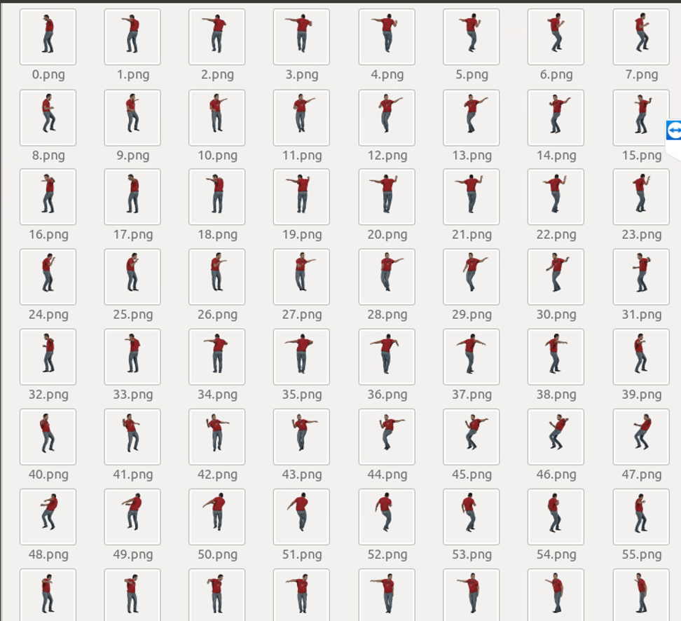
The takeaway here is that when recording camera trajectories in Unity (a common workflow given Unity’s native support for VR headsets like Meta Quest), it is critical to verify that coordinate space conventions—world, camera, and pixel space—align perfectly between Unity and your novel view synthesis framework.
Extracting Quaternions from TRS Matrices
(This section is also an extra reference note for my lab mates and me rather than core camera intuition.)
Later in my project, I needed to synchronize rotational data from recorded camera traces. However, I had only logged the 4x4 TRS matrices rather than explicit rotations like quaternions or Euler angles. While re-recording the trace with rotation data would work, we can also extract the quaternion directly from the TRS matrix.
Prerequisite: All quaternions used or computed in Unity are unit quaternions, meaning:

If a quaternion is not a unit quaternion, it does not represent a pure rotation (Unity automatically normalizes quaternions under the hood). I omitted this detail earlier to keep the initial explanations simple.
Now, let’s assume a uniform unit scale s = <1, 1, 1> to keep the algebra clean (we’ll address arbitrary scaling shortly). Under this assumption, the TRS matrix simplifies to:

We can now extract the quaternion components r = <r.x, r.y, r.z, r.w>, starting with r.w:
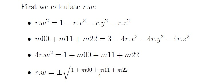
While we could theoretically solve for r.x, r.y, and r.z using the main diagonal elements alone, doing so requires three square root operations, which is both computationally slower and prone to floating-point precision loss. Since we already have r.w, we can solve for the remaining components algebraically:
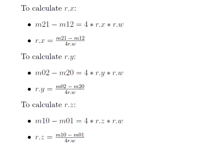
And that is how you extract a quaternion from a TRS matrix!
Now, when an actual scale s = <s.x, s.y, s.z> is present, the technique is to find the least common multiple LCM of s.x, s.y, and s.z. Then:
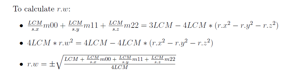
Similarly, we can find the least common multiples of s.x and s.y, s.x and s.z, and s.y and s.z to calculate the rest. I won’t write out the full algebraic expansion here as it is quite tedious.
Conclusion
That covers everything regarding simulating and replaying camera traces in Unity for novel view synthesis. Thank you for reading to the end!